Inductance with physical symmetry
Inductance of a solenoid
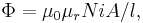
A solenoid is a long, thin coil, i.e. a coil whose length is much greater than the diameter. Under these conditions, and without any magnetic material used, the magnetic flux density  within the coil is practically constant and is given by
where  is the magnetic constant,
  the number of turns,
  the current and
  the length of the coil. Ignoring end effects the total magnetic flux through the coil is obtained by multiplying the flux density by the cross-section area
  and the number of turns :
When this is combined with the definition of inductance,

it follows that the inductance of a solenoid is given by:
A table of inductance for short solenoids of various diameter to length ratios has been calculated by Dellinger, Whittmore, and Ould[1]
This, and the inductance of more complicated shapes, can be derived from Maxwell's equations. For rigid air-core coils, inductance is a function of coil geometry and number of turns, and is independent of current.
Similar analysis applies to a solenoid with a magnetic core, but only if the length of the coil is much greater than the product of the relative permeability of the magnetic core and the diameter. That limits the simple analysis to low-permeability cores, or extremely long thin solenoids. Although rarely useful, the equations are,
where  the relative permeability of the material within the solenoid,
from which it follows that the inductance of a solenoid is given by:
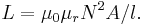
where N is squared because of the definition of inductance.
Note that since the permeability of ferromagnetic materials changes with applied magnetic flux, the inductance of a coil with a ferromagnetic core will generally vary with current.
Inductance of a coaxial line
Let the inner conductor have radius  and permeability
  , let the dielectric between the inner and outer conductor have permeability
  , and let the outer conductor have inner radius
  , outer radius
  , and permeability
  . Assume that a DC current
  flows in opposite directions in the two conductors, with uniform current density. The magnetic field generated by these currents points in the azimuthal direction and is a function of radius
  ; it can be computed using Ampère's law:
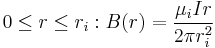
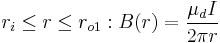
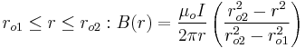
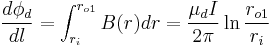
The flux per length in the region between the conductors can be computed by drawing a surface containing the axis:
Inside the conductors, L can be computed by equating the energy stored in an inductor,  , with the energy stored in the magnetic field:
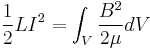
For a cylindrical geometry with no dependence, the energy per unit length is
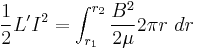
where  is the inductance per unit length. For the inner conductor, the integral on the right-hand-side is
  ; for the outer conductor it is
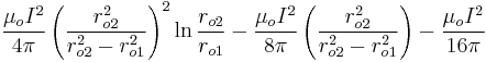
Solving for and summing the terms for each region together gives a total inductance per unit length of:

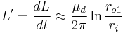
However, for a typical coaxial line application we are interested in passing (non-DC) signals at frequencies for which the resistive skin effect cannot be neglected. In most cases, the inner and outer conductor terms are negligible, in which case one may approximate
==References
- ^ D. Howard Dellinger, L. E. Whittmore, and R. S. Ould (1924). "Radio Instruments and Measurements". NBS Circular (National Bureau of Standards) C74. http://books.google.com/books?id=Xn8KbsgeFrwC&pg=PA248#v=onepage&q=&f=false. Retrieved 2009-09-07.